Shear Force and Bending Moment
An introduction to Shear Force and Bending Moments in Beams
Contents:
- Shearing Force
- Bending Moments
- Types Of Load
- Types Of Support
- The Relationship Between W; F; M.
- Apendix
1.Shearing Force:
The shearing force (SF) at any section of a beam represents the tendency for the portion of the beam on one side of the section to slide or shear laterally relative to the other portion.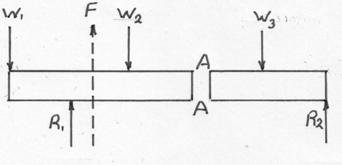
The diagram shows a beam carrying loads
 . It is simply supported at two points where the reactions are:-
Assume that the beam is divided into two parts by a section XX The resultant of the loads and reaction acting on the left of AA is F vertically upwards and since the whole beam is in equilibrium, the resultant force to the right of AA must be F downwards. F is called the Shearing Force at the section AA. It may be defined as follows:- The shearing force at any section of a beam is the algebraic sum of the lateral components of the forces acting on either side of the section. Where forces are neither in the lateral or axial direction they must be resolved in the usual way and only the lateral components use to calculate the shear force.
2.Bending Moments:
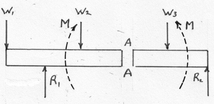
In a similar manner it can that if the Bending moments (BM) of the forces to the left of AA are clockwise then the bending moment of the forces to the right of AA must be anticlockwise. Bending Moment at AA is defined as the algebraic sum of the moments about the section of all forces acting on either side of the sectionBending moments are considered positive when the moment on the left portion is clockwise and on the right anticlockwise. This is referred to as a sagging bending moment as it tends to make the beam concave upwards at AA. A negative bending moment is termed hogging.
3.Types Of Load:
A beam is normally horizontal and the loads vertical. Other cases which occur are considered to be exceptions. A Concentrated load is one which can be considered to act at a point although of course in practice it must be distributed over a small area. A Distributed load is one which is spread in some manner over the length or a significant length of the beam. It is usually quoted at a weight per unit length of beam. It may either be uniform or vary from point to point.4.Types Of Support:

A Simple or free support is one on which the beam is rested and which exerts a reaction on the beam. It is normal to assume that the reaction acts at a point although it may in fact act act over a short length of beam. A Built-in or encastre' support is frequently met . The effect is to fix the direction of the beam at the support. In order to do this the support must exert a "fixing" moment M and a reaction R on the beam. A beam which is fixed at one end in this way is called a Cantilever. If both ends are fixed in this way the reactions are not statically determinate. In practice it is not usually possible to obtain perfect fixing and the fixing moment applied will be related to the angular movement of the support. When in doubt about the rigidity it is safer to assume that the beam is freely supported.
5.The Relationship Between W; F; M.

In the following diagram
 is the length of a small slice of a loaded beam at a distance x from the origin O
 Let the shearing force at the section x is F and at  . Similarly the bending moment is M at x and
  . If w if the mean rate of loading of the length , the total load is
  , acting approximately ( exactly if uniformly distributed) through the centre C. The element must be in equilibrium under the action of these forces and couples and the following equations can be obtained:-
Taking Moments about C . Similarly the bending moment is M at x and . If w if the mean rate of loading of the length , the total load is , acting approximately ( exactly if uniformly distributed) through the centre C. The element must be in equilibrium under the action of these forces and couples and the following equations can be obtained:- 
.................(1)
 in the limit:-
.................(2)

.................(3)

.................(4)

..................(5)
 although they may in fact represent the greatest bending moment on the beam. Consequently it is not always sufficient to investigate the points of zero shearing force when determining the maximum bending moment. At a point on the beam where the type of bending is changing from sagging to hogging, the bending moment must be zero and this is called a point of inflection or contra -flexure. By integrating equation (2) between the x = a and x = b then:-
..................(6)

...................(7)

...................(8)


